
Installation instructions for the simple dry powder mortar production line
Installation Instruction for Ribbon mixer
Zhengzhou TONGDING machinery & Equipment Co,.Ltd. is a leading company specializing in the manufacture and sales of Mixing Machines and Dryers.
Our main products include:
1) A simple and environmental friendly dry mortar production line, applicable to all kinds of powders.
2) Dry mortar production line units.
3) Complete set of stone paint production lines.
4) Complete production line of dryers.
5) Machines for thermal insulation mortar and complete set of production lines.
6) Transmission equipment series products.
7) Series of products of packaging equipment.
8) Dust removal equipment, a series of products and various accessories.
TONGDING persists in implementing the strategy of improving the competitive ability of our products, relying on a strong R&D team that keeps forging ahead in an innovative way, aiming to be at the forefront of technology, and constantly updating our HI-TECH innovation capability of the corporation.
Combining domestic and foreign market demands with development trends, TONGDING introduces an advanced international technology, adapting and applying these trends to our products and manufacturing.
We stress our international technical cooperation and communication, and integrate advanced technology from Germany, Sweden, and Finland. We keep the service idea of “Create More Value To Our Customers”, with the times to provide our high quality products, global service and advanced technology for our customers.
Installation of the required tools and spare items:
1、100AOne of three phase four wire plastic shell circuit breakers(connect total sluice),63ATwo three phase miniature circuit breakers(connect hoist and air compressor),40ATwo three phase miniature circuit breakers(used two roots connect hoists),4PMiniature circuit breaker 40A一个(connect valve package machine),6 Square core copper wire10mUsed to connect each switch,Small electric box(400*500*200)pcs,10mm Four expansion screws,Percussion drill,10mm One of the bits of a bit,Guide 1m,12-14,14-17,19-22,22-24Open spanner,250mmAn active wrench,iron wire10m,A pair of hand pliers,A wallpaper knife,One word cross screwdriver each,Electric rubber cloth 2 pcs,Butter a barrel, a butter gun,0.9m3/min Air compressor one(Joint matching),10mmPlastic transparent trachea30m,Fast trachea three pass one,Iron10mmTwo sets of trachea joints,A blow (wind) gun, with 2 rolls of raw material.
2、The mainframe motor connection line is4Square three core copper wire,first screw conveyor motor wire is 2.5Square three core copper wire ,package machine motor wire is 2.5Square 4 core copper wire.The cable is fixed according to the distance between the location of the machine and the power bus.
3、If the reducer of the mixer is a cycloidal needle reducer, it needs to be bought.46#Engine oil (antiwear hydraulic oil))4 liters and two barrels
Installation steps
1、According to the layout of the user site, the multifunctional mixer main engine is placed in the preselected place. Remarks: several factors should be taken into account when selecting the location of the mixer.
1) raw material storage area and finished product storage area are more convenient.
2) reserve the equipment maintenance channel. The general maintenance channel requires a width of 0.8 meters. (overall schematic diagram)
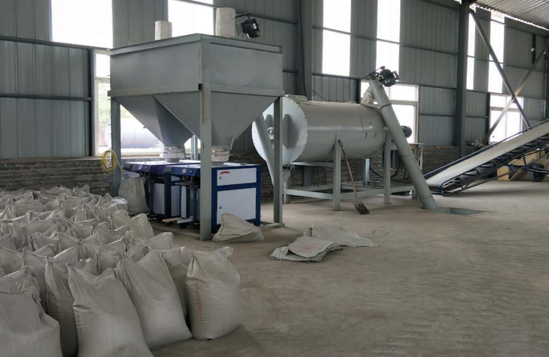
2、After placing the mixer in place, it is necessary to stir the center of the feed inlet of the main engine, and the edge of the main engine is 0.95 meters away from the edge of the screw feeder. The bottom pit size is as shown in the figure: 0.53M (long) *0. 53 m (wide) *0.7 m (deep)
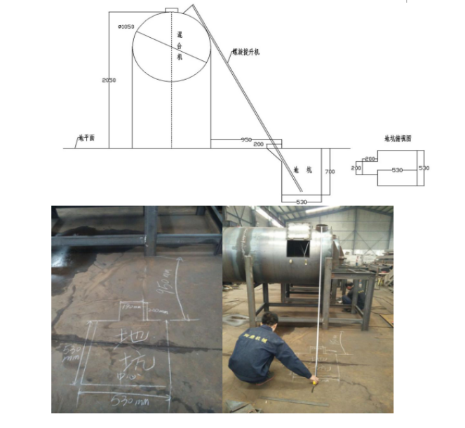
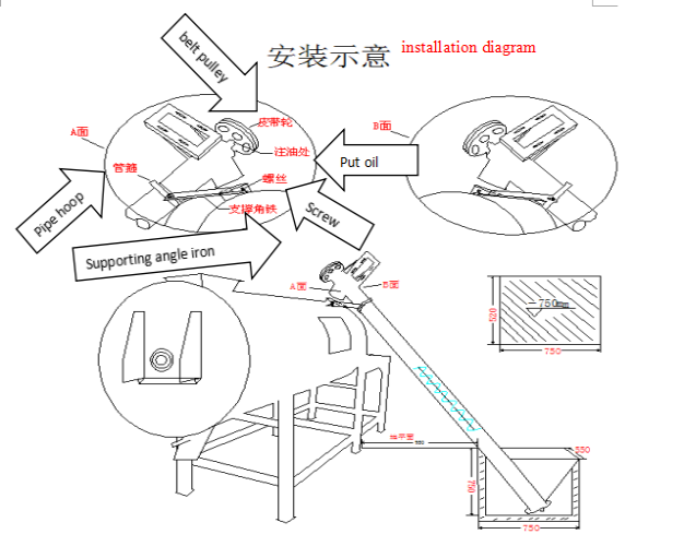
Remarks: after the pit is dug up, if there is water seepage in the pit, waterproof treatment is necessary.
Dig the pit and put it on the bottom of the hoist. (as shown in the picture)
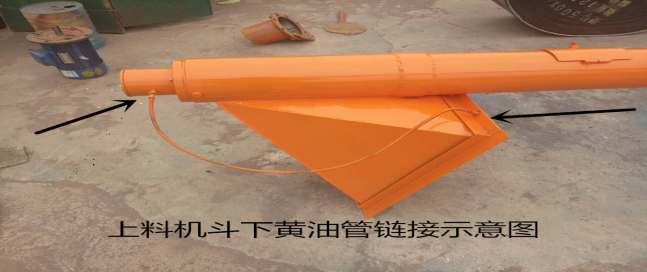
↑schematic diagramof a butterinrigation link under the bucket ofthe feeder
3、After the pit is dug up, the screw feeder is put into the pit, and the hopper on the feeder is level or higher than the ground level (within 10cm of distance control).
4、After putting it on, use the hoop to connect the screw feeding machine and the mixing main machine, and the screws are fastened. The outlet of the screw feeding machine is connected with the feeding port of the main stirring machine by soft connection and tightly secured with iron wire. After connecting, dust and breathable cloth bag (dust bag) will be used to tighten the other upper feeding port on the mixing machine to prevent dust.
5、After connecting, find the manual butterfly valve, connect two times with screws, lift the manual butterfly valve, and stir the main engine outlet. Note: when the manual butterfly valve is placed, please note that the spanner of the manual butterfly valve is opened up.
6、After putting it on, use the hoop to link the two screw feeder and the finished product warehouse. The material outlet of the screw feeding machine is connected with the inlet of the finished product bin by soft connection, and is fastened with iron wire.
7、After the link is good, use the fine cloth with dustproof and breathable to cover the other two feeding ports on the finished warehouse and the other mouth of the mixing host, and tighten it with wire.
8、Move the automatic packaging machine to the bottom of the finished product warehouse. After adjusting the position of the packing machine with the convenience of packing, the cloth bag on the upper part of the packing machine is taken out with the bottom of the finished warehouse, and the wire is fastened with wire, and it must be tightened.
9、link each motor wire. Pay attention to positive and reverse. The mixing main station is located in the direction of the discharge port, and the stirring shaft rotates counter clockwise. Automatic packaging machine according to the direction of the arrow marked on the chassis. The tip direction of the helical blade of the screw feeder is in the positive direction. (spiral up loader from the bottom up, the belt counter clockwise rotation is positive).
10、Precautions for operating use
1.)When starting the engine, the main power of the mixer should be opened, and the main engine is strictly prohibited. Next, a hoist is opened. After the power is switched on, it can be fed. The mixer set the time according to the properties of the material used by the customers. After the agitation, the two times the power supply of the hoist is opened and the manual butterfly valve at the outlet of the main engine is opened.
2)When the material enters the finished product warehouse, open the manual valve below the finished warehouse, open the automatic packaging machine, and then pack it.
3)daily maintenance: reducer regularly refueling, it is best to replace once a year, half a year to check the oil level, not enough time to add. Main bearings and screw loader and butter are added once a week.
If you still have any doubts or want to know the detailed process, please contact this number. +86 13673306161